
Blog

How to Choose the Right CNC Cutting Tools?

Choosing CNC cutting tools is not a catalog exercise. It is a decision about material, machine rigidity, workholding, cutting conditions, and the finish you need. A carbide end mill may suit a rigid setup, while a sharp, polished edge can help prevent aluminum from sticking to the flutes. Small details matter: tool overhang, coolant delivery, and even a loose fixture can change the cut.

Machining researcher Tony Schmitz’s work offers a useful foundation for understanding cutting mechanics. I cannot verify a direct quotation from him on choosing CNC cutting tools, so the following is an editorial principle, not his verbatim statement: “Match the tool to the material, setup, and finish—not just the advertised speed.” That distinction matters. A tool that performs well in one shop may chatter or wear quickly in another. Test cuts and measured results are more dependable than assumptions.

This guide explains how to compare tool materials, coatings, geometries, and sizes. It also considers feeds and speeds, tool life, and common signs of trouble, such as burrs, squealing, or a rough surface. Look closely at the chips. Their shape and color can reveal whether cutting conditions need attention. No selection chart replaces judgment; even a sound recommendation may need adjustment on your machine. The aim is a practical, evidence-led choice that balances accuracy, productivity, and cost.
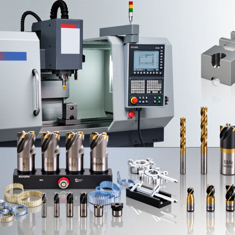
How to Choose the Right CNC Cutting Tools?

Identify the Workpiece Material and Machining Operation

Before choosing a cutter, identify the workpiece—not just its broad category. ISO 513:2012 groups materials as steel, stainless steel, cast iron, non-ferrous metals, heat-resistant alloys, and hardened materials. That classification is a useful starting point, but the actual grade matters. A soft aluminum alloy and a silicon-rich casting can behave very differently at the cutting edge. Check hardness, abrasiveness, and whether the material tends to form long, sticky chips. Small details matter.

Then match the tool to the operation. Rough milling needs a strong edge and room for chips; finishing usually benefits from sharper geometry and a stable setup. Drilling, slotting, and interrupted cuts each create different heat and load patterns. A cutter that works well on a continuous pass may chip when it repeatedly enters and exits the workpiece. The U.S. Geological Survey’s 2024 Mineral Commodity Summaries estimated 2023 global tungsten mine production at 78,000 metric tons. That figure is not a machining-performance measure, but it highlights why carbide tool material and supply deserve consideration. I would still verify the material certificate and test a short cut: shop assumptions can be wrong. Start with a conservative speed, inspect the chips, and watch for edge wear or built-up material before increasing feed.

Match Tool Material and Geometry to the Cutting Task

How to Choose the Right CNC Cutting Tools?

Match tool material to the workpiece and cutting conditions, not just the machine’s maximum speed. ISO 513:2012 classifies work materials into six groups: steel, stainless steel, cast iron, non-ferrous metals, heat-resistant alloys, and hardened materials. This is a useful starting map, not a complete recipe. Coated carbide suits many production cuts; high-speed steel can be tougher for small tools or interrupted cuts. Ceramics tolerate heat but need a stable setup. They can chip suddenly.

Geometry matters just as much. A sharp, positive-rake edge helps reduce cutting forces in aluminum, where a built-up edge can spoil the surface. For hard alloys or interrupted cuts, a stronger edge may resist chipping. Match flute count and chip space to the material: gummy chips need room to escape, while a fine finish may call for a different edge and feed. Keep an eye on the sound and the chips.

ISO 13399 provides standardized descriptions for cutting-tool data, helping shops compare dimensions and features consistently. It does not predict performance in a particular setup. Test one variable at a time: tool grade, geometry, speed, or feed. That check can reveal a mismatch. A shiny tool is not always a healthy tool; inspect the edge under magnification, and record wear alongside cycle time. The best choice may still need adjustment.

Select Tool Dimensions and a Compatible Toolholder

Choose tool dimensions around the feature, material, and machine’s available clearance. A cutter that is too large can leave a corner radius the drawing will not accept. Too small, and machining time may climb. Match the cutting diameter to the slot or pocket, then check flute length against the full cutting depth. Keep stickout short enough to clear clamps and walls. Long overhang can increase deflection and chatter. Small detail, big effect. I still recheck it.

The holder must match the spindle interface, not just the cutter shank. ISO 7388-1 specifies a 7:24 steep-taper interface; ISO 26623-1 covers polygonal taper interfaces. These standards describe different connection geometries, so they are not interchangeable. Confirm the holder’s collet range, gauge length, retention method, and maximum speed against the machine manual. For a deep pocket, a slim holder may improve access, but reduced rigidity can compromise finish. A quick clearance check in the setup model helps, though real fixtures sometimes sit differently. Check the actual setup.

Set Cutting Parameters for the Tool and Machine

Set cutting parameters from the tool, workpiece, and machine—not from a catalog’s ideal conditions alone. Start with the tool maker’s recommended speed and feed range, then check spindle limits, available power, holder stiffness, and coolant delivery. For turning, calculate spindle speed from cutting speed and workpiece diameter; for milling, also account for tooth count and engagement. A small diameter change can raise spindle speed sharply. Verify the result against the machine’s actual limits.

Use a conservative trial cut on the real setup. Listen for chatter, inspect chips, and check the edge after a short run. ISO 3685:1993 uses 0.3 mm average flank wear as a common tool-life criterion for carbide turning tests; it offers a measurable stop point, not a universal production target. ISO 230-2 provides methods for evaluating machine-tool positioning accuracy, which matters when tight tolerances depend on repeatable motion. I still treat calculated settings as a starting point: workholding, runout, and worn bearings can change the result. Record the stable speed, feed, depth of cut, wear, and surface finish, then adjust one variable at a time. A quiet cut is useful evidence, but not proof of a good setting.

How to Choose the Right CNC Cutting Tools? — Set Cutting Parameters for the Tool and Machine

Estimated spindle speeds for a 10 mm solid-carbide end mill, calculated from representative starting cutting speeds.

These estimates use RPM = (1,000 × cutting speed in m/min) ÷ (π × tool diameter in mm). Actual parameters depend on tool geometry and grade, workpiece condition, rigidity, coolant, and machine limits. Check tool and machine specifications before cutting.

Check Tool Life, Accuracy, and Operating Conditions

Choosing CNC cutting tools starts with the job, not the catalog. Match the tool material and geometry to the workpiece, cut depth, and required finish. For long production runs, compare expected tool life with the cost of tool changes and rejected parts. For short runs, a more durable tool may not justify its price. Small clues matter.

Check wear during a run, not only after a tool fails. A polished flank, chipped edge, or rough surface can signal different problems. Measure sample parts at set intervals, especially when tolerances are tight. If dimensions drift, inspect the tool and setup before changing several settings at once. Tool life is not a fixed number; feed, speed, and material variation can shift it. I still find that a tool’s actual life sometimes differs from the estimate.

Accuracy also depends on operating conditions. Check spindle runout, toolholder cleanliness, and workpiece clamping before cutting. Coolant flow and chip evacuation matter too; packed chips can mark a surface or damage an edge. A tool that performs well in a light finishing pass may struggle in a deep slot. Keep notes on the tool, material, settings, and wear observed. The record may be imperfect, but it helps make the next choice less of a guess.

How to Choose the Right CNC Cutting Tools? - Check Tool Life, Accuracy, and Operating Conditions

Tool Material Common Workpiece Applications Tool Life Considerations Accuracy and Surface Finish Operating Conditions Best Fit
High-speed steel (HSS) General-purpose machining of mild steel, aluminum, and other relatively easy-to-machine materials. Typically wears faster than carbide at higher cutting speeds, but can tolerate impact and may be resharpened. Can produce good results when sharp and properly supported; edge wear can gradually affect dimensions and finish. Useful at lower cutting speeds and in setups where toughness or tool flexibility is important. Lower-speed operations, simpler jobs, and applications where a tough, resharpenable tool is practical.
Cemented carbide Steel, stainless steel, cast iron, aluminum, and many non-ferrous materials, with grade and geometry selected for the workpiece. Often supports higher cutting speeds and longer production runs than HSS; life depends on heat, wear, chipping, and cutting conditions. Can maintain dimensions and finish at production rates when tool runout, deflection, and wear are controlled. Requires a sufficiently rigid machine, holder, and workholding setup; choose coating and geometry for the material and operation. A versatile choice for many CNC turning, milling, and drilling operations.
Ceramic Commonly used for high-speed machining of cast iron and selected hardened or heat-resistant alloys. Can operate at high temperatures, but the cutting edge may chip under impact, vibration, or unstable cutting. Can provide consistent results in stable cuts; edge damage can cause a sudden loss of accuracy or surface quality. Generally best for rigid setups and continuous cuts; follow the insert grade’s guidance on coolant and interrupted cutting. Stable, high-speed production applications suited to a ceramic grade.
Cubic boron nitride (CBN) Hardened ferrous materials, including hardened steels and cast irons. Designed for demanding hard-machining applications; life is affected by hardness, cutting speed, edge preparation, and cut stability. Can support accurate hard turning and a fine finish when the machine and workpiece are rigid and the edge remains intact. Use a suitable CBN grade and a stable setup; avoid conditions that cause excessive impact or vibration. Hard turning and finishing of hardened ferrous parts.
Polycrystalline diamond (PCD) Aluminum alloys, copper alloys, composites, and other non-ferrous or abrasive materials. Can provide long life in suitable non-ferrous applications; it is generally not selected for machining steel at typical cutting temperatures. Can produce a fine finish and hold dimensions in appropriate materials when the tool is sharp and the setup is stable. Choose edge geometry for the material; consider abrasive fillers, built-up edge, and the required surface finish. High-volume machining of suitable non-ferrous materials and abrasive composites.

Selection note: Tool-life values are not universal. Establish a consistent end-of-life criterion—such as excessive flank wear, chipping, dimensional drift, or unacceptable surface finish—and verify it with a controlled trial under the intended machine, workholding, coolant, and cutting conditions. For accuracy, also check tool runout, machine rigidity, tool deflection, and workpiece clamping.