
Selecting the right Frequency Vfd is not simply a matter of matching horsepower. It is an engineering decision that affects energy use, motor life, process stability, and operator safety. The International Energy Agency reports that electric motor systems consume roughly half of global electricity. Even a small efficiency improvement can therefore produce measurable savings across pumps, fans, compressors, and conveyors.
The correct choice begins with the load profile. A centrifugal pump may need variable torque control, while a conveyor can demand high starting torque at low speed. Check the motor nameplate, rated current, voltage, base frequency, overload requirement, and braking conditions. Then examine the installation environment. Dust, heat, moisture, long cable runs, and poor ventilation can quickly turn an apparently suitable drive into a maintenance problem. The U.S. Department of Energy recommends evaluating complete motor systems, not isolated components, because control settings and mechanical conditions strongly influence performance.
Standards matter. IEC 61800 provides an important framework for adjustable-speed power drive systems, while NEMA guidance supports motor and drive compatibility in North American installations. Harmonic distortion, electromagnetic compatibility, functional safety, and enclosure ratings also deserve attention. Do not trust horsepower alone.
A practical selection should compare continuous current, overload capacity, control method, communication protocols, and service support. Manufacturers often publish efficiency and application data, but field conditions can differ sharply. That gap deserves honest review. A drive that performs well in a clean test room may fail beside a hot, dusty production line. This guide explains how to compare those variables and choose a Frequency Vfd with greater confidence.
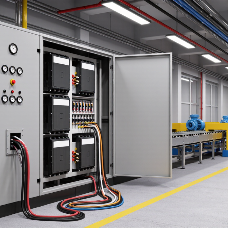
Choosing the right frequency VFD starts with the motor nameplate, not the machine’s advertised power. Record the motor voltage, rated kW, full-load amperes (FLA), phase, and base frequency. The VFD output voltage must match the motor connection. A mismatch can cause weak torque, overheating, or insulation stress.
FLA is often the most important sizing value. Select a drive that supports the motor’s actual FLA, including the required overload rating. Do not size the VFD by kW alone. Two motors with identical power ratings may have different current demands. Check the supply phase as well. A single-phase input and three-phase motor application may need specific drive approval and derating. Installation conditions matter too. High ambient heat, poor ventilation, and frequent starts can reduce usable capacity.
During commissioning, compare measured current with the nameplate value at normal load. I once found a correctly rated drive running hot because the enclosure trapped heat. The calculation looked right, but the installation was not. That experience still shapes my checks. Confirm whether the application needs constant torque or variable torque control. Pumps and fans often behave differently from conveyors or crushers. Review acceleration time, braking needs, and low-speed torque before final selection. A small safety margin is useful, but oversized drives can reduce cost efficiency and complicate protection settings. Always verify the final choice against the drive manual and qualified electrical practice.
A VFD should match the motor’s full-load current, not only its horsepower. This matters because electric motor systems consume about 46% of global electricity, according to the International Energy Agency’s energy-efficiency analysis. In heavy-duty service, conveyors, mixers, crushers, and loaded hoists can demand sharp starting torque. Select a drive rated for at least 150% of its normal output current, often for 60 seconds. Confirm the exact overload duration in the technical manual. It varies.
Speed changes the thermal picture. A motor running slowly may receive less cooling from its shaft-mounted fan. Dust, high ambient temperature, long cable runs, and frequent starts can reduce usable capacity. IEC 60034-1 emphasizes that motor ratings depend on duty conditions, temperature rise, and operating time. Therefore, record the motor nameplate current, actual load profile, peak torque, and lowest operating speed before choosing the VFD. A tidy spreadsheet can still mislead. Real loads are rarely tidy.
Tips: Leave practical margin, but do not oversize blindly. Check 150% overload current, carrier frequency, braking needs, enclosure rating, and motor cooling. For uncertain loads, measure current during startup and the hardest working cycle. One missed peak can cause nuisance trips. A larger frame is not always the better answer; correct data is.
How to Choose the Right Frequency VFD for Your Application?
Set the Speed Range: Check Motor Cooling Below 30 Hz
When selecting a frequency VFD, define the motor’s real operating range. A machine may run smoothly at 20 Hz, but smooth operation does not guarantee safe cooling. Standard motors often use shaft-mounted fans. Below 30 Hz, the fan may move much less air while the motor still produces substantial torque. Heat can accumulate inside the windings, especially during slow, continuous operation.
Check the motor’s load profile, not only its rated power. Conveyors, mixers, and compressors can demand high torque at low speed. Measure current, casing temperature, and running time during a practical trial. A thermal sensor connected to the drive can provide valuable protection. In some installations, an independently powered cooling fan is a better solution. Do not assume 30 Hz is a universal limit. Motor design, enclosure, ambient temperature, and duty cycle all matter. The manufacturer’s thermal curve should guide the final setting.
There is a detail that is easy to miss. Motor speed is not exactly the same as output frequency because slip changes with load. We once treated frequency as the only speed reference, and the result was less accurate than expected. Review acceleration time, minimum frequency, overload capacity, and braking requirements together. If low-speed torque is essential, test the complete motor and drive combination under the heaviest realistic load. A short bench test can hide long-term heating problems.
Set the Speed Range: Check Motor Cooling Below 30 Hz
For a self-cooled motor with a shaft-mounted fan, airflow is approximately proportional to motor speed. On a 50 Hz motor, operation at 30 Hz provides about 60% of rated fan airflow, while operation below 30 Hz reduces cooling further. Confirm the motor manufacturer's low-speed torque and thermal limits, and consider forced ventilation or derating for continuous operation at low frequency.
How to Choose the Right Frequency VFD for Your Application?
Choosing the right frequency VFD begins with the control mode, not only the power rating. The motor, load behavior, speed range, and starting torque all matter. V/f control suits fans, pumps, and simple conveyors with steady loads. It is economical and easy to commission. However, speed can drop when the load changes sharply.
Sensorless vector control provides stronger torque at low speed without an encoder. It works well for mixers, compressors, hoists with moderate demands, and conveyors that start under load. Accurate motor data is essential. Incorrect nameplate values can cause unstable current or weak starting performance. I have seen a convenient setup fail because the motor data was entered from memory.
Closed-loop vector control adds encoder feedback to measure actual shaft speed. This mode supports precise speed, torque, and position control. It fits elevators, winding equipment, precision feeders, and machines that must hold speed during sudden load changes. The extra sensor needs correct alignment, shielding, and maintenance. A loose encoder cable can create faults that look like drive problems.
Do not select the most advanced mode automatically. It may increase wiring, setup time, and service requirements. Review the application’s lowest operating speed, overload duration, stopping method, and feedback needs. A short test with the real motor and load is often more reliable than a perfect spreadsheet. That part is easy to overlook.
| Selection Dimension | V/f Control | Sensorless Vector Control | Closed-Loop Vector Control | Practical Selection Guidance |
|---|---|---|---|---|
| Basic operating principle | Maintains a programmed voltage-to-frequency ratio to regulate motor speed. | Uses a motor model and output-current feedback to estimate rotor position and torque. | Uses a speed or position encoder to provide direct shaft feedback for precise control. | Select the simplest method that satisfies the required speed, torque, and positioning performance. |
| Typical applications | Fans, pumps, blowers, simple conveyors, and general-purpose speed control. | Conveyors, mixers, compressors, hoists with suitable braking, and machines requiring improved torque control. | Cranes, elevators, winders, extruders, servo-like machinery, and applications requiring accurate speed or position. | Match the control mode to the mechanical load profile rather than choosing by motor power alone. |
| Speed regulation | Usually adequate for non-critical speed control; accuracy varies with load, slip, and motor temperature. | Typically offers substantially better speed regulation than V/f without a physical encoder. | Provides the highest speed accuracy because actual shaft speed is measured continuously. | Use closed-loop control when speed error directly affects product quality or machine safety. |
| Low-speed torque | Limited compared with vector methods; low-speed torque may require boost settings and careful tuning. | Strong low-speed torque is available when the motor data and autotune are correctly configured. | Excellent low-speed torque and torque control, including controlled operation near zero speed. | For high starting torque or heavy breakaway loads, prefer vector control and verify overload requirements. |
| Torque response | Basic response; suitable where rapid torque changes are not critical. | Fast dynamic torque response for many industrial speed-control applications. | Fastest and most predictable torque response when feedback and tuning are properly implemented. | Choose closed-loop control for frequent acceleration, deceleration, load shocks, or torque regulation. |
| Operation at zero speed | Generally not intended to produce sustained rated torque at zero speed without additional measures. | Can provide limited zero-speed torque, depending on the drive, motor model, tuning, and application. | Can hold torque at zero speed when correctly configured, subject to motor heating and drive ratings. | For suspended loads or long dwell periods, confirm brake logic, thermal limits, and safety functions separately. |
| Feedback requirement | No speed encoder required. | No encoder normally required; accurate motor nameplate data and autotuning are important. | Requires a compatible encoder or resolver, feedback cable, interface, and correct installation. | Avoid feedback hardware when the application does not need its performance benefits. |
| Motor compatibility | Commonly used with standard three-phase induction motors; compatibility is generally straightforward. | Works with many induction motors and, on suitable drives, permanent-magnet or synchronous motors. | Requires matched motor, feedback device, drive interface, and commissioning parameters. | Confirm motor type, rated current, base frequency, encoder resolution, and feedback protocol before selection. |
| Commissioning complexity | Low; basic frequency, ramp, voltage, and protection settings are usually sufficient. | Moderate; motor data, autotuning, current limits, acceleration, and deceleration parameters must be set correctly. | High; requires feedback alignment, tuning, mechanical checks, and verification of direction and loss-of-feedback behavior. | Allow additional engineering and commissioning time as control performance requirements increase. |
| Energy-saving potential | Often highly effective for variable-torque fan and pump loads because speed reduction can greatly reduce power demand. | Can improve efficiency under changing loads through better torque production and speed control. | Can optimize performance in demanding systems, but encoder and control benefits should justify added complexity. | For centrifugal pumps and fans, evaluate the complete system curve and operating schedule. |
| Overload capability | Often suitable for normal-duty variable-torque loads; heavy-duty requirements must be checked separately. | Commonly selected for constant-torque and heavy-duty loads, subject to the drive's published current rating. | Suitable for demanding dynamic loads when the drive, motor, braking system, and feedback are correctly sized. | Size by motor current and overload duty, not only by nominal kilowatts or horsepower. |
| Installation and maintenance | Simplest wiring and fewer feedback-related components. | Moderate wiring and maintenance requirements; no encoder generally reduces mechanical installation work. | More components and cable-routing requirements; feedback alignment and shielding are important. | Consider available service skills, spare parts, cable length, grounding, and electromagnetic compatibility. |
| Best overall choice | Choose when cost, simplicity, and reliable variable-speed operation are the main priorities. | Choose when strong low-speed torque and improved regulation are needed without installing an encoder. | Choose when precise speed, torque, zero-speed holding, or position control is essential. | Validate the final selection against motor data, load inertia, duty cycle, braking needs, ambient conditions, and applicable safety requirements. |
Choosing the right frequency VFD begins with the electrical environment, not only motor power. A drive may match the motor perfectly and still create unacceptable harmonics or electromagnetic interference. IEEE 519 evaluates harmonic distortion at the point of common coupling, where the facility connects to the utility. Measure at the PCC. Do not rely only on the drive’s input-current rating.
In field applications, I check the transformer capacity, short-circuit ratio, cable length, motor loading, and nearby sensitive equipment. A line reactor can reduce current distortion and protect the DC bus from supply disturbances. Passive filters may provide stronger correction, while active filters adapt to changing loads. However, every filter introduces cost, heat, maintenance, or possible resonance. No single filter solves every installation.
IEC 61800-3 addresses EMC performance for adjustable speed drive systems. Its requirements depend on the intended environment, such as residential, commercial, or industrial locations. Select the correct drive category, then verify installation practices. Use shielded motor cables, short bonding paths, suitable cable glands, and a properly designed protective-earth connection. Separate power and control wiring where practical. Noise travels strangely. Increasing the switching frequency may reduce audible motor noise, but it can increase leakage current and radiated emissions. I have seen installations pass bench tests and fail after long cables were added. That experience makes site measurements essential, especially for common-mode voltage, conducted emissions, and harmonic current under real operating loads.