
A 2510 Connector is commonly used as a compact wire-to-board connector in control panels, LED assemblies, appliances, and small electronic devices. The name often refers to a 2.54 mm pitch design, although manufacturers may use the term differently. That detail matters. A connector marked “2510” may vary in pin count, housing direction, contact plating, and current rating.
Interconnect expert Eric Bogatin states, “Every interconnect is a component.” His point applies directly here. A 2510 Connector is not merely a plastic housing with metal contacts. It affects assembly speed, electrical continuity, vibration resistance, and service reliability. In practical use, an engineer may inspect the locking ramp, crimp barrel, wire gauge, and mating force before selecting one. A loose crimp can create intermittent power loss. A mismatched pitch can damage the header.
This guide explains what a 2510 Connector is, how its structure supports reliable connections, and where it is typically installed. It also examines crimping methods, polarity control, current capacity, and common selection mistakes. The label alone is not enough. Product drawings and manufacturer specifications should confirm every critical dimension. Some assumptions remain easy to make, especially when similar housings look identical. Careful verification is still the safer approach.
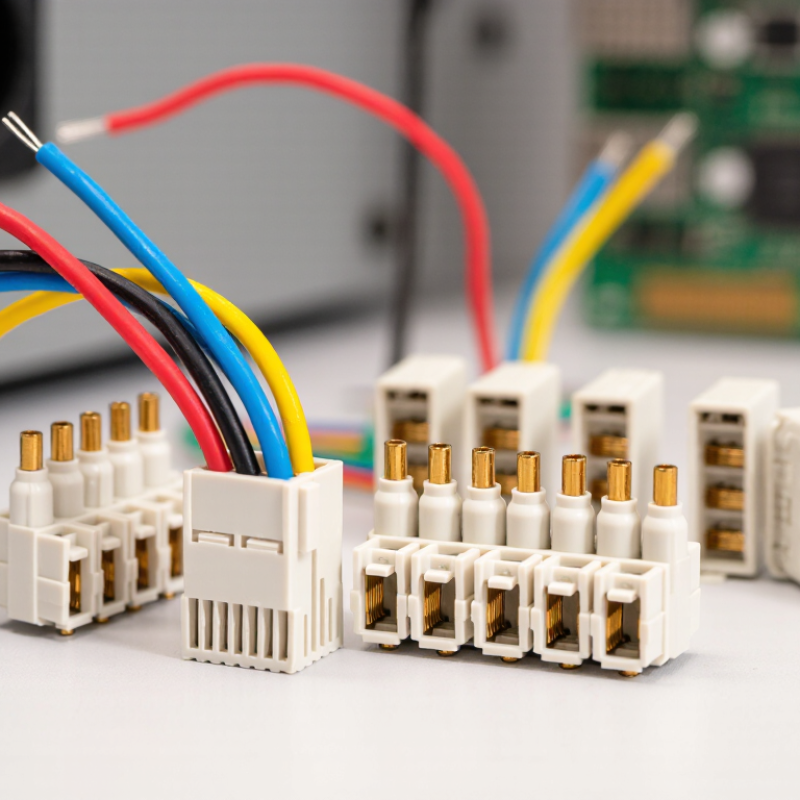
A 2510 connector is a compact wire-to-board connector commonly used on electronic circuit boards. The name usually refers to a pin pitch of about 2.54 millimeters, or 0.1 inch. It is not always a universal standard. Different suppliers may use the same term for slightly different housings, terminals, or locking features.
The connector normally includes a plastic housing and crimp contacts. Wires are attached to the contacts, then inserted into the housing. A matching header is soldered to the circuit board. Many versions use two or more positions, while some designs support single-row or double-row layouts. The housing may include a friction lock, which helps prevent accidental separation during vibration or movement.
In practical assembly, polarity and pin order deserve close attention. A small connector can still carry power, signals, or both. Reversing the plug may damage sensitive components. Check the pitch, wire gauge, current rating, contact plating, and mating orientation before production. A caliper helps confirm spacing when drawings are unclear. Do not rely on the name alone.
These connectors appear in LED modules, battery wiring, control panels, sensors, and compact consumer equipment. Their low profile saves board space. However, they are not suitable for every load. High current, heat, or repeated plugging may require a stronger connector design. The term “2510” can be confusing, and that confusion should be treated as a design risk.
A 2510 connector is commonly designed around a 2.54 mm pitch, allowing contacts to sit in a compact, organized pattern. Its housing may use one or two rows, depending on the required circuit count and available board space. Small but practical.
The plastic body normally includes polarized guides or a locking shape. These features help prevent reversed insertion during assembly. Metal contacts are selected for conductivity, spring force, and resistance to corrosion. Wire versions usually use crimp terminals, while board versions use straight or right-angle pins. The exact configuration depends on pin quantity, wire size, current, voltage, and operating temperature.
In real assembly work, the connector should be configured before the cable is cut. Check the cavity numbering, contact orientation, and exposed wire length. A poorly positioned crimp can look acceptable but fail a gentle pull test. That detail is easy to miss. Test continuity across every circuit, then inspect the housing for incomplete locking. Mating force should feel firm, not excessively tight. Designers also need clearance around the latch, especially in stacked boards or narrow enclosures. Although the 2510 format is widely used, its electrical limits are not universal. Different contact materials and housing grades can change performance. Relying only on the name is risky; verify the technical drawing and approved test conditions for each configuration.
| Data Dimension | Typical 2510 Connector Specification | Design or Usage Notes |
|---|---|---|
| Connector Type | Wire-to-board crimp connector | Used to connect discrete wires to a printed circuit board through a plug and receptacle housing. |
| Nominal Pitch | 2.54 mm (0.100 in) | The pitch is the center-to-center distance between adjacent contacts and is the defining dimensional feature of this connector family. |
| Contact Arrangement | Usually single-row; some configurations are available in multiple rows | The row arrangement must match the PCB footprint, mating housing, and required circuit density. |
| Number of Positions | Commonly 2 to 12 positions | Position counts vary by design. Unused positions may be left unpopulated when the housing supports them. |
| Contact Spacing Calculation | Contact center span = (number of positions − 1) × 2.54 mm | For example, a 6-position single-row version has a center span of 12.70 mm, excluding housing walls. |
| Mounting Style | Through-hole PCB, surface-mount PCB, or panel-mounted variants | Through-hole versions generally provide stronger mechanical retention; surface-mount versions support automated assembly. |
| Mating Orientation | Vertical, horizontal, or right-angle | The orientation is selected according to cable exit direction, enclosure clearance, and PCB layout. |
| Terminal Connection | Crimped female or male contacts | A properly formed crimp creates both an electrical connection and mechanical strain resistance without soldering the wire. |
| Typical Wire Size | Approximately 22–28 AWG, depending on the terminal design | The conductor size, insulation diameter, and crimp-tool setting must match the selected contact. |
| Housing Material | Molded thermoplastic, commonly nylon or a similar insulating polymer | The housing provides insulation, contact positioning, polarization, and mechanical guidance during mating. |
| Contact Material | Copper alloy, often phosphor bronze or brass | Copper alloys provide electrical conductivity and spring properties required for repeated mating. |
| Contact Finish | Tin plating is common; gold plating may be specified for demanding environments | The plating affects oxidation resistance, contact stability, insertion force, and durability. |
| Typical Current Rating | Up to approximately 2 A per contact in many small-wire configurations | The actual allowable current depends on contact size, wire gauge, temperature rise, number of energized positions, and housing design. |
| Typical Voltage Rating | Up to approximately 250 V AC/DC for suitable configurations | The working voltage must be verified against insulation spacing, pollution level, applicable standards, and the final equipment design. |
| Temperature Range | Commonly about −25°C to +85°C; high-temperature variants may extend beyond this range | The lowest-rated component, including housing, terminal plating, wire insulation, and PCB material, determines the usable range. |
| Polarization | Keyed housing, guide features, or asymmetrical mating geometry | Polarization prevents incorrect orientation and helps align contacts before full insertion. |
| Retention Method | Friction fit, locking lance, latch, or board-retention feature | A positive latch is preferred where vibration, cable movement, or frequent servicing could loosen the connection. |
| PCB Footprint | 2.54 mm pad or hole pitch with manufacturer-defined pad diameter and keep-out area | The footprint must include the correct hole size, pad dimensions, polarity marking, housing clearance, and solder-mask openings. |
| Typical Applications | Sensors, LED modules, control boards, small motors, fans, battery leads, and embedded equipment | It is suitable for low- to moderate-power signal and power interconnections where compact size and serviceability are important. |
| Configuration Selection | Choose position count, row count, contact gender, mounting style, orientation, plating, and wire range | The plug, receptacle, contacts, PCB footprint, and crimp tooling must be selected as a compatible system. |
| Installation Sequence | Strip wire, crimp terminal, inspect crimp, insert contact into housing, and mate with PCB header | Avoid excessive insulation damage, incomplete terminal insertion, bent contacts, and wiring errors during assembly. |
| Main Design Advantages | Compact 2.54 mm spacing, modular position counts, detachable wiring, and simple assembly | The connector provides a practical balance between circuit density, manual handling, and manufacturing cost. |
A 2510 connector usually refers to a wire-to-board connector with a 2.54 mm pitch. The “25” commonly indicates 2.54 mm spacing, while “10” often describes a ten-position housing. However, naming practices vary between manufacturers. Always check the drawing, terminal layout, and electrical rating.
Its main use is compact power and signal distribution. Engineers install it in LED lighting, small control panels, household appliances, battery packs, and embedded devices. A ten-position version can carry several sensor signals beside positive and negative power lines. The locking housing helps prevent loose connections when equipment vibrates. It is practical, but not automatically rugged.
The global connector market reached about 84.23 billion dollars in 2023, according to Fortune Business Insights’ 2024 industry report. That growth reflects demand from electronics, vehicles, automation, and renewable-energy equipment. A 2510 connector fits many low-voltage assemblies because its 2.54 mm spacing supports dense layouts and affordable cable preparation. Field experience shows a recurring mistake: designers choose it by pitch alone. That assumption is risky. Current, temperature, wire size, mating cycles, and insulation clearance also matter. In dusty equipment, an unsealed connector may fail earlier than expected. In high-vibration systems, additional retention may be necessary. Some applications need a different connector entirely.
A 2510 connector commonly refers to a 2.54 mm pitch wire-to-board connector. It usually uses crimped terminals inside a single- or double-row housing. Check the exact pin count first. “2510” is not a universal specification, so dimensions can vary between manufacturers. Mordor Intelligence’s 2024 connector market analysis estimates continued growth in global connector demand, driven partly by compact control equipment and industrial electronics. That growth makes correct assembly more important, not less.
Start by matching the housing, terminal type, wire gauge, and contact layout. Cut the wire cleanly, then strip only the length specified for the terminal. Too much exposed copper can cause shorts. Too little prevents a reliable crimp.
Place the conductor in the crimp barrel and use a calibrated crimping tool. A firm crimp should hold the conductor without crushing it. Perform a gentle pull test. It is a small check, but it catches many weak connections.
Insert each terminal until its locking lance clicks into place. Follow the connector’s polarity marks and confirm the pin sequence before mating. Finally, use a multimeter to check continuity and accidental shorts.
IPC/WHMA-A-620 workmanship guidance emphasizes secure crimps, proper insulation support, and acceptable conductor placement. I still recheck polarity manually; connector housings can look correctly aligned while being reversed.
Avoid forcing the plug. A damaged latch may pass today’s test and fail after vibration.
Choosing a 2510 connector starts with confirming its meaning. In many applications, “2510” indicates a 2.54 mm pitch family, not ten positions. Check the drawing, cavity count, mating direction, and keying before ordering. A 2024 connector-industry forecast estimated the global connector market at approximately US$84 billion in 2023, showing how widely small interconnects support industrial electronics. Size alone does not prove suitability.
Match the terminal to the wire gauge and expected current. Then verify insulation diameter, contact resistance, operating temperature, and mating cycles. For vibration-prone equipment, choose a positive lock and add strain relief. IPC/WHMA-A-620 provides widely used workmanship criteria for crimped wire assemblies, including conductor placement and crimp quality. A loose crimp may look acceptable but heat under load. That detail is easy to miss.
Maintenance should be simple and regular. Inspect the 2510 connector for darkened terminals, pushed-back contacts, cracked housings, and loose wires. Dust can raise contact resistance. Use approved dry cleaning methods, not sharp tools or aggressive abrasives. Measure continuity after maintenance, then test the circuit under its normal load. I would also record the mating count and inspection date. My earlier mistake was treating a successful continuity test as proof of reliability. It is only one checkpoint. Temperature, vibration, and repeated insertion can expose weaknesses later. Replace questionable terminals rather than forcing them back into position.