What Is a Flexible Circuit Board?
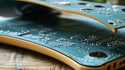
A flexible circuit board is an electronic circuit built on a thin, bendable substrate. Unlike rigid boards, it can fold, curve, or fit into narrow spaces. This structure often uses polyimide film, copper traces, protective coverlays, and carefully placed components. It is not simply a rigid board made thinner. Its materials and manufacturing methods require different design decisions.
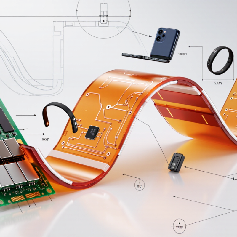
In practical products, a flexible circuit board may connect a camera module, display, medical sensor, or compact battery system. It can reduce wiring, save space, and lower assembly weight. Picture a phone hinge opening thousands of times while a copper path continues carrying signals. That movement creates real engineering pressure. Bend radius, copper thickness, adhesive selection, heat, and vibration all affect reliability.
Designers usually review industry guidance, including IPC-related flexible-circuit standards, before releasing production files. Experienced teams also test dynamic bending, insulation resistance, solder-joint strength, and dimensional stability. Laboratory results matter. So does manufacturing feedback. A design may look excellent on screen but fail near a sharp corner. That lesson is easy to miss.
The phrase “flexible” can also mislead readers. These circuits are bendable within defined limits, not endlessly stretchable or foldable. Repeated movement may still cause fatigue, especially around vias and component joints. This guide explains how flexible circuit boards are constructed, where they perform well, and which limitations deserve attention. The technology is powerful. It is not magic.
Definition and Core Characteristics of a Flexible Circuit Board
What Is a Flexible Circuit Board?
Definition and Core Characteristics of a Flexible Circuit Board
A flexible circuit board is an electronic interconnection made on a bendable insulating film. It carries electrical signals through thin copper traces. Unlike a rigid board, it can fold, twist, or fit around curved surfaces. Common insulating materials include polyimide and other heat-resistant polymer films. A protective coverlay shields the traces from moisture, abrasion, and accidental contact.
Its core characteristic is controlled flexibility, not unlimited bending. Every design has a minimum bend radius. Bending below that limit can crack copper traces or weaken plated holes. Static flex applications bend during assembly, while dynamic flex applications move repeatedly during operation. Thickness, copper type, trace width, and layer count all influence performance. A thinner circuit usually bends more easily, but it may handle less mechanical stress.
Practical evaluation requires more than checking whether the board bends. Engineers inspect signal integrity, thermal exposure, connector strain, and repeated-motion durability. A small wearable device may need a circuit only a fraction of a millimeter thick. A robotic joint may require carefully routed traces and reinforced bend zones. Testing should reflect real movement, temperature changes, and installation pressure. This is where early assumptions can fail. A circuit that passes a simple folding test may still develop hidden fatigue after thousands of cycles.
What Is a Flexible Circuit Board?
A flexible circuit board is an electronic circuit built on a bendable insulating substrate, commonly polyimide, instead of a rigid board. Its core characteristics include low profile, reduced weight, three-dimensional routing capability, and reliable performance in applications where space or movement is limited.
The chart shows common nominal copper thicknesses used in flexible circuit construction. Copper thickness is typically specified by weight per square foot: 0.5 oz is approximately 17.5 μm, 1 oz is approximately 35 μm, and 2 oz is approximately 70 μm. Actual stack-up thickness depends on the substrate, coverlay, adhesive, plating, and design requirements.
Main Materials and Layered Construction
A flexible circuit board is a thin electrical assembly designed to bend, fold, or move inside a product. Unlike a rigid board, it can follow curved housings and reduce the need for wires and connectors. In practical assembly work, this saves space and can improve reliability around hinges or moving joints. It still needs careful handling. Repeated bending in the wrong area may damage copper traces.
The base material is commonly polyimide, which tolerates heat and repeated flexing. Some cost-sensitive designs use polyester film instead. Copper foil forms the conductive paths. It may be rolled and annealed for dynamic bending, or electrodeposited for less demanding applications. Adhesive bonds copper to the dielectric film, although adhesive-free constructions can provide better flexibility and dimensional stability. A coverlay protects the traces, leaving only selected pads exposed. Surface finishes help preserve solderable contact areas.
Layered construction controls both performance and durability. A single-layer circuit has one copper layer and suits simple connections. Double-layer designs place copper on both sides, with plated holes linking them. Multilayer versions add dielectric films, adhesive layers, and carefully aligned copper patterns. Stiffeners may reinforce connector ends without restricting the bend zone. I have seen designs fail because a stiffener extended too far. That detail is easy to miss. Bend radius, copper grain direction, and layer symmetry deserve verification before production. Mistakes often begin in the drawing.
How Flexible Circuit Boards Are Manufactured
What Is a Flexible Circuit Board?
How Flexible Circuit Boards Are Manufactured
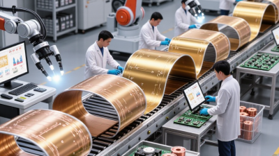
A flexible circuit board uses thin copper traces on a bendable insulating film, often polyimide. Its structure supports folding, moving connections, and tight installation spaces. Manufacturing begins with a copper-clad film. Engineers select its thickness according to current, flexibility, and expected bending cycles.
Production teams clean the film before applying a light-sensitive resist. A circuit image is transferred onto the coated surface, usually through controlled ultraviolet exposure. Unwanted copper is etched away, leaving the required traces. The process demands careful timing. Over-etching can narrow a trace and reduce its electrical reliability. Under-etching can create shorts between adjacent conductors.
Small holes are drilled mechanically or with a laser, depending on the material and feature size. Plating then connects different copper layers through these holes. A coverlay protects the traces, while carefully placed openings expose soldering areas. Heat and pressure bond the layers together. Operators must control alignment closely; even a slight shift can affect a connector or stiffener.
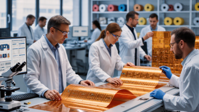
After lamination, each circuit is shaped through precision cutting. Inspectors check line width, hole position, surface quality, and electrical continuity. Flexible boards also need bending tests that match their real installation conditions. A board may pass a flat inspection and still fail after repeated movement. That remains an easy issue to underestimate. Manufacturing decisions should reflect actual bend radius, temperature, and assembly stress rather than drawings alone.